Model Electronic Railway Group
The Leading Society for Model Railway Electronics
CBUS®, A Layout Control Bus from MERG
Revised 2nd March 2024
Introduction
The CBUS® system was developed over 4 years by Mike Bolton and Gil Fuchs and introduced with specifications and an initial range of kits in 2007. (NB. CBUS is a registered trademark of Dr Mike Bolton). Since then the system has been further developed by many MERG members into a very comprehensive Layout Control Bus. The system is intended to simplfy the wiring of a model railway whilst enhancing the control capabilities. The CBUS system uses a specially developed protocol to communicate between input and output modules. For the most part CBUS uses CANBUS to communicate over a 2 wire (plus power supply) link around the layout although use is also made of Ethernet, USB and WiFi communications when needed. Provision is made in the system for operation of layout accessories, point motors, signals etc. from traditional control panels, lever frames, or from a suitable programme on a computer. The MERG DCC system uses CBUS to link cab handsets, and/or mobile phones/tablets/computers to the Command station. The system is continually developing with recent designs for modules able to incorporate signal and point interlocking or to read RFID tags (Radio Frequency IDentification) fitted to rolling stock. Compatible computer control software is available as follows:
Rocrail also offer some kits for compatible control modules. The CBUS system does not require a computer to run and for simple functions on basic modules can also be set up and configured without use of a computer. However use of the more complex functions of the system does require a computer for setup and configuration. A comprehensive configuration utility is available for this. Configuration is also possible from within JMRI.
A more detailed description of the CBUS system is available on the CBUS details page. Full details of the current and original CBUS designs are available to MERG members when logged in.
Kits
Kits for a range of modules are available to MERG members. Members should check the Technical Bulletin and Kit pages in the members area for technical descriptions, build instructions and availability of kits. CBUS kits are listed in 3 categories, Basic, Advanced and Explorer. The Basic kits can be set up and configured without use of a computer as mentioned above, while the Advanced kits require use of a computer for set up. The Explorer kits are provided to interface to hobby sytems such as the Arduino and Raspberry Pi to allow users to create more complex CBUS functionality with their own programming. In addition to the individual kits listed below we offer two beginner bundles specifically selected to help a beginner in assembling, testing and configuring CBUS kits. Special supplementary instructions are included and working through these will give a novice in CBUS the understanding to use the CBUS system on thir layout. Brief descriptions of most of the current kits are given below. For various reasons we cannot supply to non-members. When the first designs were produced it was common practice for MODEL Railway auxiliaries to be supplied from a nominal 16V AC transformer, hence those designs were primarily intended to operate from such an AC supply. Since then Model Railway power supplies have mostly changed to DC Switch mode power supplies and all current CBUS modules are designed for a 12V DC supply.
General purpose output module (CANOUT) Kit 28, Basic.
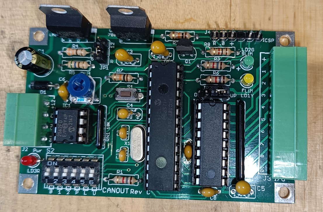
This module provides 8 general purpose outputs that can be used to operate relays, LEDs or other electronic modules. The outputs can be set for pulse or steady state as required. The design includes facilities for configuration without a computer using the SLiM model.
General purpose input module (CANINP) Kit 29, Basic.
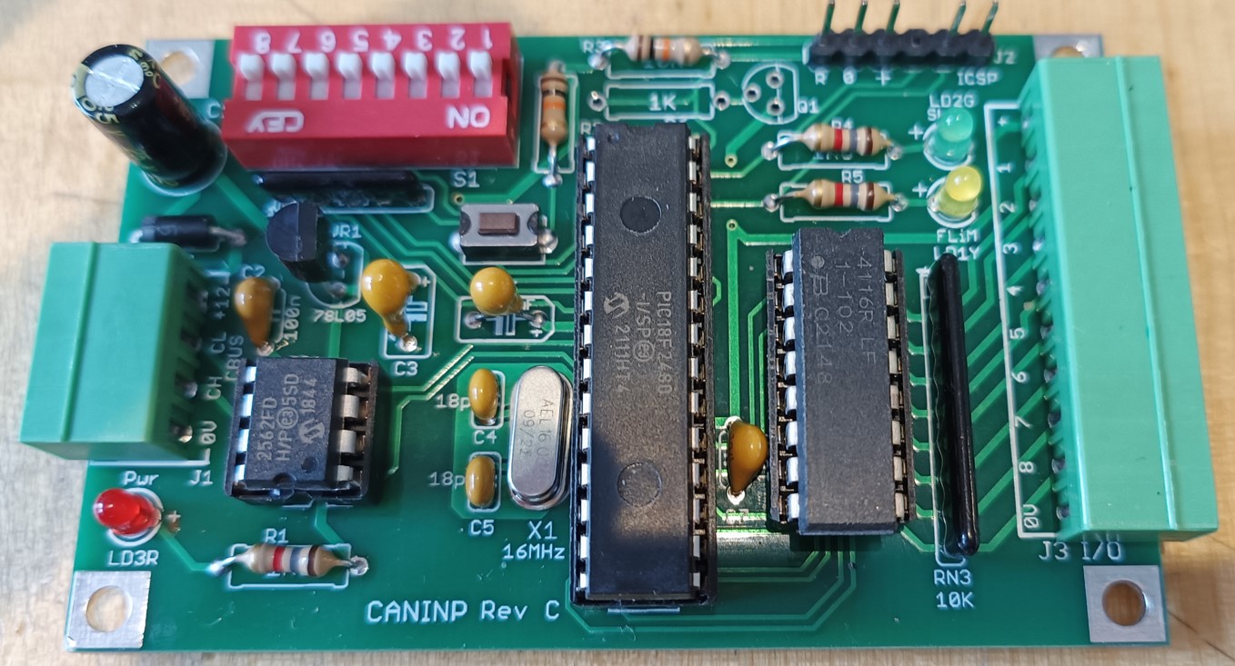
This module provides 8 input channels that can be use for feedback from the layout to the cntrol system. It is suitable for use with many train on track detectors, such as the DTC TOTIs, kits 50 and 56A, for indicating track occupancy and for use with point position detectors etc. The inputs are designed to go active when connected to the 0V of the power supply.
The design includes facilities for configuration without a computer using the SLiM model.
Solenoid Turnout Driver (CANSOL) Kit 94, Basic.
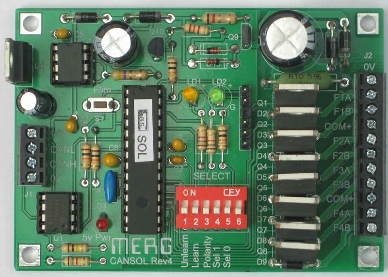
These modules have a built in Capacitor Discharge Unit (CDU) and are optimised for the operation of solenoid point motors requiring a high current pulse. Each decoder has 4 outputs for twin coil solenoids and each output is capable of operating two point motors as required for crossovers.
This is a basic category kit and includes facilities for configuration without a computer using the SLiM model.
Computer connection module, USB (CANUSB4) Kit 80A
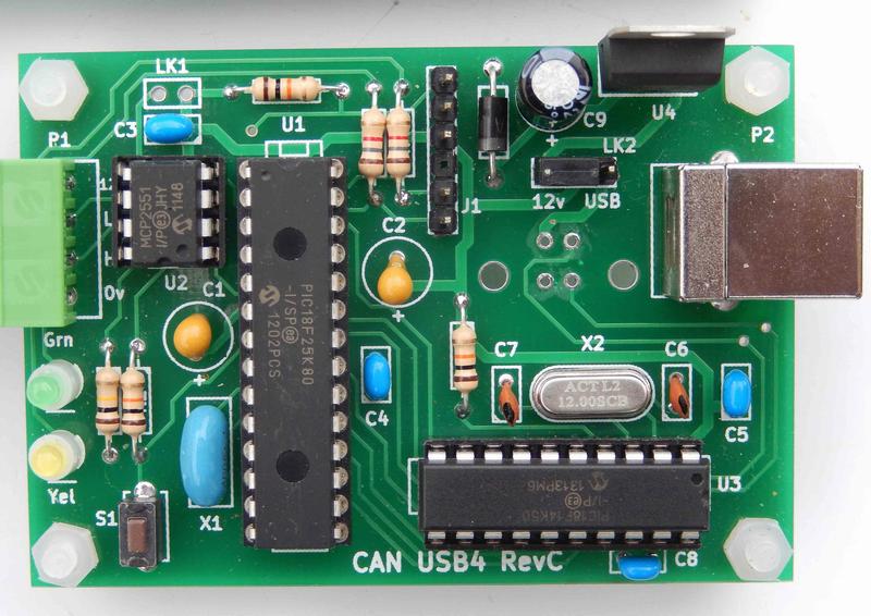
This module is designed to simply connect the CBUS system to a computer using the computers USB connector. This allows for system configuration using the FLiM model and/or operation of the layout from computer programmes such as JMRI or Rocrail. The module can be powered from a 12V DC supply or direct from the computer USB connection at 5V. The module does not need configuration.
Servo motor driver (CANVSERVO) Kit 13, Advanced.
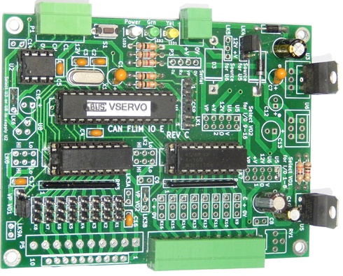
This kit is supplied with hardware to drive 8 servo motors and to accept 8 inputs and software is supplied to suit. The servo motors can be adjusted for end positions and operating speed. They are suitable for operation of points and semaphore signals. Note MERG can also supply a variety of mounting brackets suitable for the common SG90 type servos. This is an advanced category kit and needs a computer for configuration.
Control Panel encoder/driver (CANPAN) Kit 97, Advanced.
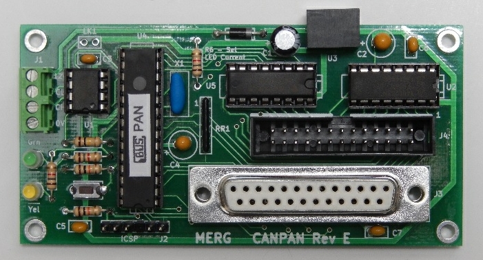
This is single module that carries out the functions required for most control panels with a maximum of 32 switches and 32 LEDs. For larger panels additional CANPANs can be used. However large the panel, only 4 wires are required to connect it to the layout This is an advanced category kit and needs a computer for configuration.
General purpose output and input module (CANVOUT) Kit 11, Advanced.
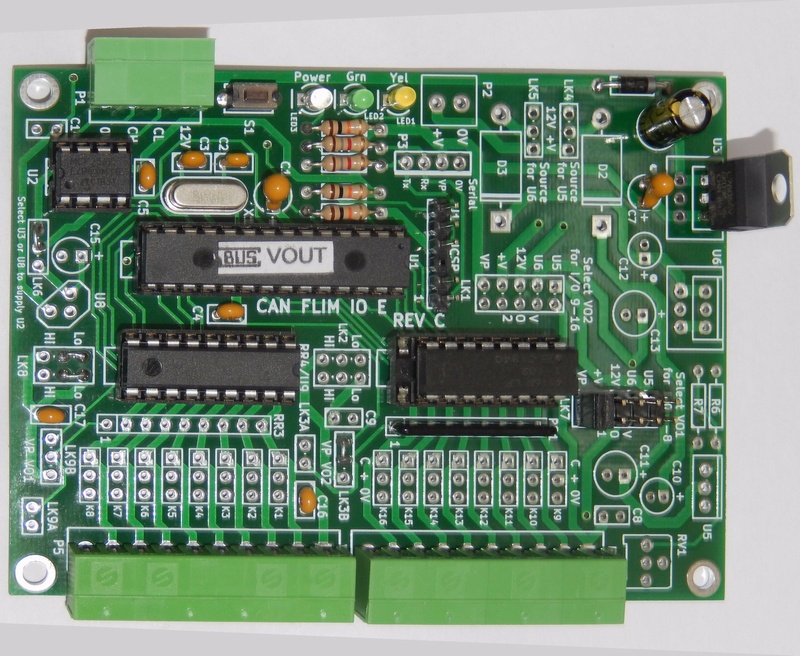
This is single module that provides 8 outputs for driving relays and accessories like a CANOUT and also 8 inputs for such things as point position or track occupancy. This is an advanced category kit and needs a computer for configuration.
Bi-polar output module with 8 inputs (CANV4BIP) Kit 14, Advanced.
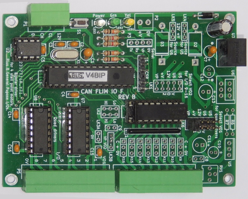
A Combination Module with 4 outputs for driving motorised turnouts and stall motor turnouts such as Tortoises and Fulgurex units, plus 8 inputs for feedback or switch inputs. This is an advanced category kit and needs a computer for configuration.
Multi input/output module (CANMIO) Kit 98A, Advanced.
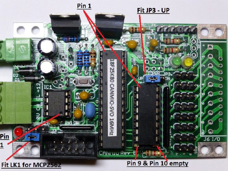
This circuit board has hardware designed to be buildable for most combinations of input and output circuits up to 16 in total. In this kit the software is supplied to build it for operation of 8 servo motors and with the option to add 8 inputs as for the CANVSERVO. Alternative software, available to download, can be loaded if the kit is built for other options. This is an advanced category kit and needs a computer for configuration.
Arduino CAN Shield Kit 110, Explorer.
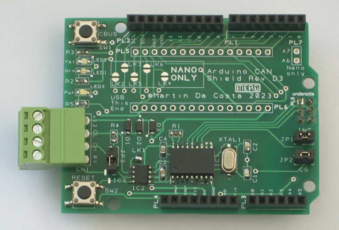
This is a standard ARDUINO format shield that can be built for the ARDUINO UNO R3 and the ARDUINO MEGA. As built it can be inserted on top of one of these ARDUINOs to add a standard MERG CAN Bus port. The shield can also optionally be built as a mounting platform for an ARDUINO NANO. All options are covered in the Building instructions. The purpose of this item is to provide a base for generating CBUS modules using the Arduino. The design is such that when used with the UNO R3 or MEGA other shields can be added on top of this one to do other things. The functionality that can be added to CBUS with the Arduino is as wide as the imagination of the user.
Computer connection module for Raspberry Pi (CANPiCAP) Kit 86, Explorer.
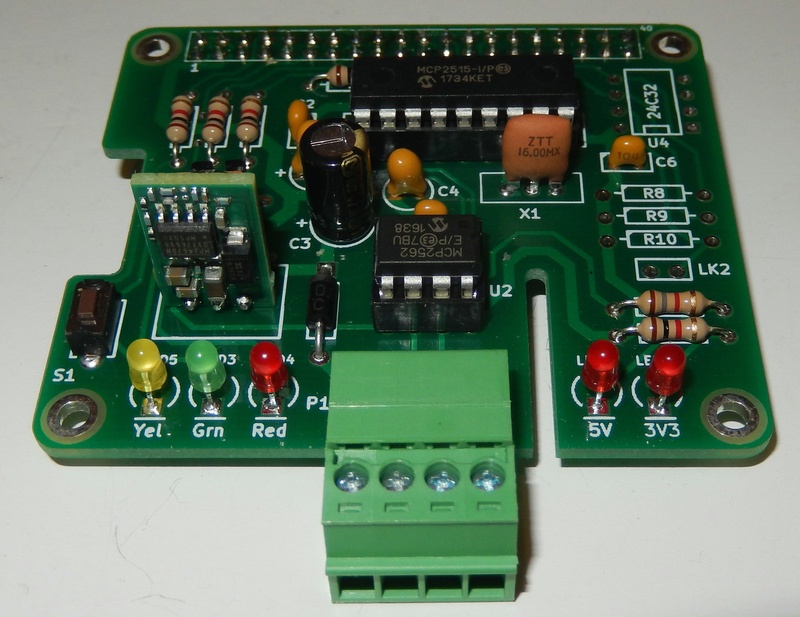
This module connects the CBUS system to a Raspberry Pi computer (RPi). In a similar way to other Raspberry Pi enhancements the module mounts directly to an RPi making a CBUS module with many uses. The RPi can be used to run JMRI providing complex interlocking or layout operation from a touch screen. It can also link by WiFi to other computers or phones allowing train driving from the phone or system setup from a laptop without the need to plug in a USB cable. The module is designed for a 12V DC supply and will provide the power needed by the attached RPi.
CBUS Activity Monitor (CANACT) Kit 90
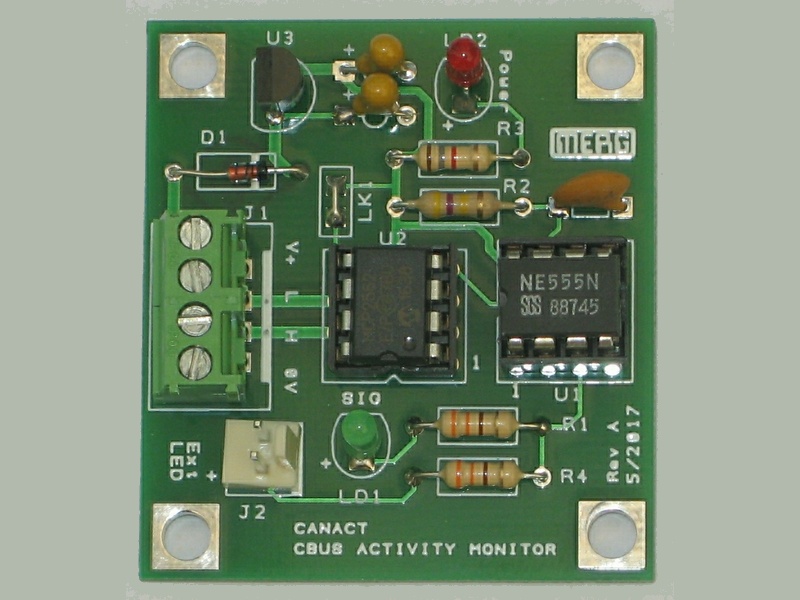
This module is essentially a simple test aid and just monitors the CBUS for activity and flashes an LED for each message seen It operates from the 12V DC supply and no configuration is needed.
CBUS Test module (CANGIZMO) Kit 492.
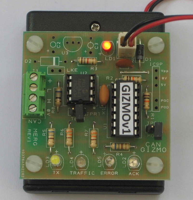
This is a more comprehensive test module that can be used to monitor the bus just like the CANACT but more importantly can test each other module built to show that it's CBUS communication is working properly before attaching it to the bus. It is supplied setup for self contained battery power but can be built for external 12V DC supply if desired.
LCB Experimenters Kit Kit 490
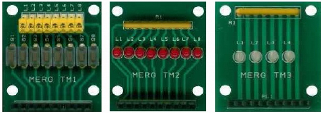
This kit includes 3 small boards which are especially useful to CBUS novices allowing modules to be tested and configured in a test environment before use on the layout. The TM1 carries 8 switches to provide test inputs. The TM2 carries 8 LEDs that can indicate when each output is active. The TM3 is for use with bi-polar output modules and carries 4 bi-colour LEDs that will show the output polarity when module is set up for operation of stall motors such as the Tortoise.
LCB Test boards, Kit 491
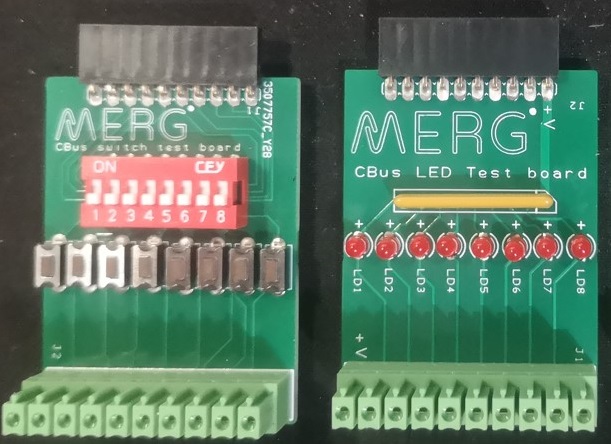
This kit includes 2 small boards which are especially useful to CBUS novices allowing modules to be tested and configured in a test environment before use on the layout. They are updated versions of the TM! and TM2 included in kit 490 with connectors added to simplify connection to current CBUS modules.
LCB Test board, Kit 493
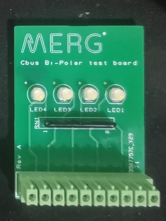
This kit includes 1 small board which is designed to test modules with bi-polar outputs, especially the CANV4BIP. It is an updated version of the TM3 included in kit 490 with a connector added to simplify connection to the CANV4BIP.
Test module for CANPAN (TM7) Kit 497
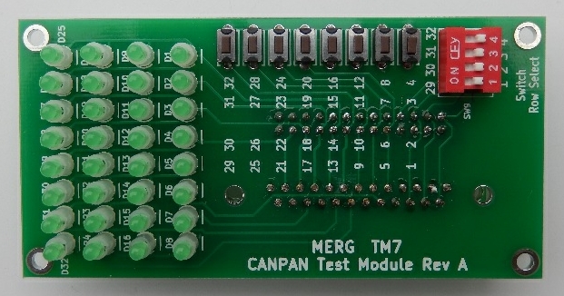
This kit is similar in concept to the Experimenters Kit but larger and designed to fit directly to a CANPAN. The board includes a set of 32 LEDs so that the state of all outputs can be seen, along with 8 push buttons that can be used with a selector switch to activate any of the 32 inputs.
Copyright
Copyright for items on this website is retained by the authors. Further licensing details are available on our copyright page.
The use or misuse for the sale, design, supply, process, installation, delivery, test, repair, servicing, and alteration of the designs, instructions, computer code, photographs, circuits, and any other information that appear on this web site is entirely at the risk of the user or visitor to the web site. The information is made available in good faith without warranty of any kind strictly on the basis that no liability will attach to the Model Electronic Railway Group (MERG), its officers and members.