MERG DCC System Demonstration
This uses MERG's DCC Command Station (kit 91) connected to MERG's DCC Handset (kit 92) via the CANRJ22 connector (kit 92V). A CAB Holder (kit 673) is used to hold the Handset.

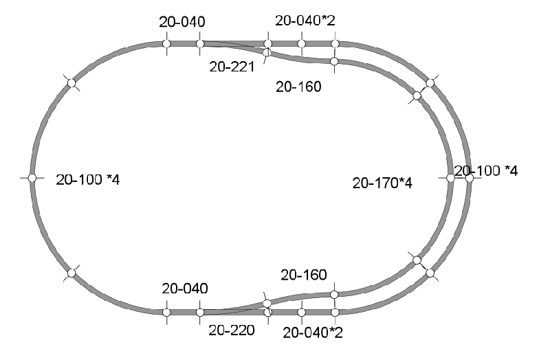
The track is divided into 7 sections and the DTC8 DCC Block Detector (kit 56) used to show track occupancy. The DTC8 is split into 4 boards, each with 2 coils and these are fed into the CBUS System
In addition a CANACC8 (kit 88) is connected to the Command Station. The CANACC8 has a TM2 board from the CBUS Experimenter's kit (kit 90). This TM2 is from an early prototype and has the LEDs in two rows. It is used to show the orientation of the points, which are controlled from the DCC Handset.
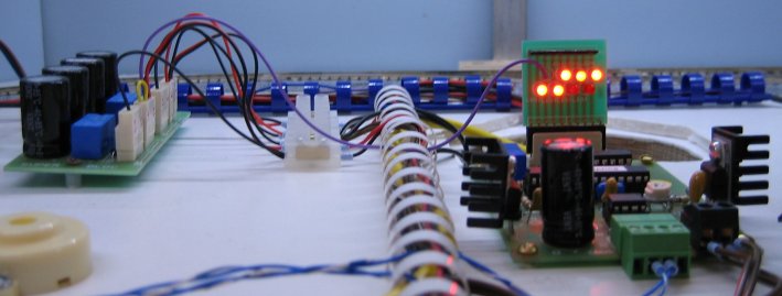 Instead of an LED in the top left position, a wire is taken to a PD3 point motor driver (kit 37a) and this controls both Kato points on the demonstration layout.